2.4 System Operation Evaluation
The system operation evaluation consists of two functions: economic operation evaluation and energy flow operation evaluation. Through these two analytical assessments, it displays the energy efficiency ratio, transport coefficient, operational efficiency, and energy flow structure of each equipment.
2.4.1 Economic Operation Evaluation
Using "flowcharts," a root-cause analysis model is constructed to analyze the upstream and downstream factors affecting the system's key energy efficiency ratios. The content of the flowcharts varies by energy station type, with pre-built flowcharts currently available for water-cooled energy stations and ground-source heat pump energy stations.
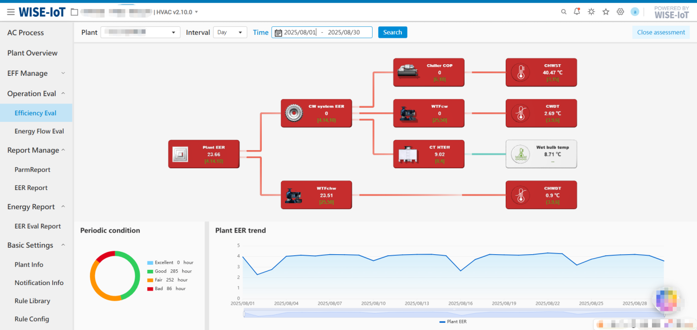
The page is divided into two main areas: the upper section displays real-time energy efficiency data and metric thresholds for the system or equipment type shown in the flowchart, while the lower section shows the periodic operating conditions and historical energy efficiency/parameter trends of the selected module in the flowchart. The periodic operating conditions and historical trends are based on historical data and support statistical display for different time periods.
If both cooling and heating are present, the periodic operating conditions will separately calculate the operating time of cooling and heating within different threshold ranges.
The trend chart supports statistical data display by monthly, daily and hourly granularity:
① Monthly – One data entry per month, default query shows the most recent 12 months' data, with a maximum query range of 3 years.
② Daily - One data entry per day, default query shows the most recent month's data, with a maximum query range of 24 months.
③ Hourly - One data entry per hour, default query shows the most recent 7 days' data, with a maximum query range of 31 days.
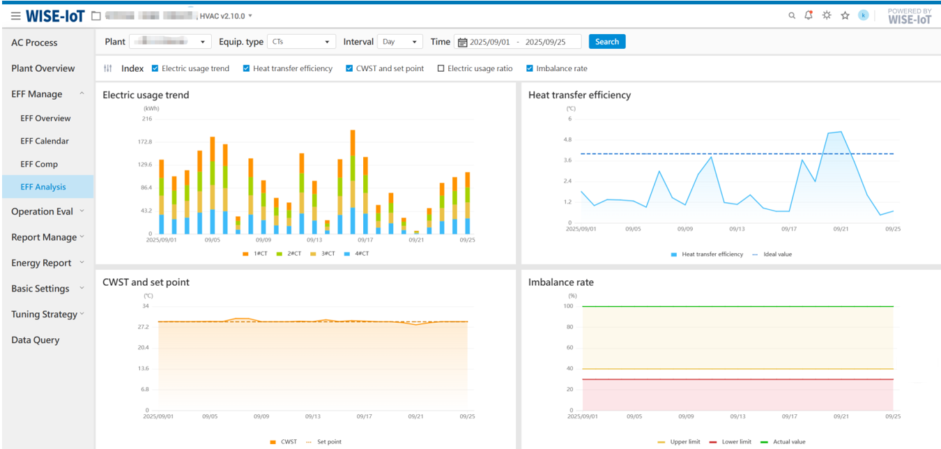
Water-Cooled Energy Station Economic Operation Evaluation
UI Reference:
Key Notes:
-
Clicking on any module in the flowchart will dynamically update the periodic operating conditions and trend chart below.
-
When clicking on [Cooling Tower Heat Exchange Efficiency], [Chilled Water Supply Temperature], [Cooling Water Temperature Difference], [Outdoor Wet-Bulb Temperature], or [Chilled Water Temperature Difference], only the trend chart is displayed below, without periodic operating conditions.
-
When clicking on [Cooling Water Pump Transport Coefficient] or [Chilled Water Pump Transport Coefficient], the periodic operating conditions are displayed according to the operating time with three threshold ranges (Excellent/Good/Bad).
-
When clicking [Energy Station System Efficiency Ratio], [Refrigeration System Energy Efficiency Ratio], or [Chiller Unit Energy Efficiency Ratio], the periodic operating conditions are displayed according to the operating time with four performance thresholds (Excellent/Good/Fair/Bad). The energy station system statistics are displayed by default.
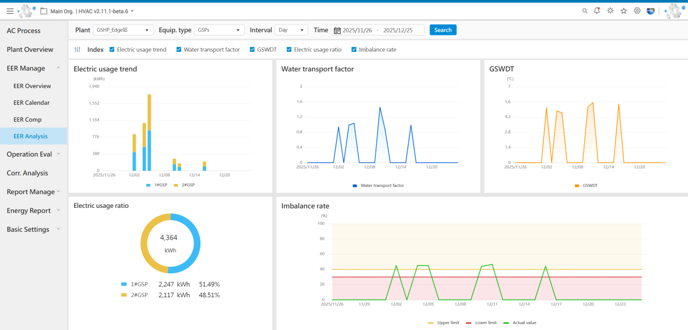
Ground Source Heat Pump Energy Station Economic Operation Evaluation
UI Reference:
Key Notes:
-
Clicking on any module in the flowchart will dynamically update the periodic operating conditions and trend chart below.
-
When clicking on [Air Conditioning Side Supply Water Temperature], [Outdoor Temperature], [Ground Source Side Water Temperature Difference], or [Air Conditioning Side Water Temperature Difference], only the trend chart is displayed below, without periodic operating conditions.
-
When clicking on [Ground Source Side Water Pump Transport Coefficient] or [Air Conditioning Side Water Pump Transport Coefficient], the periodic operating conditions are displayed according to the operating time with three threshold ranges (Excellent/Good/Bad).
-
When clicking [Energy Station System Efficiency Ratio], [Ground Source Heat Pump System Energy Efficiency Ration], or [Ground Source Heat Pump Group Energy Efficiency Ratio], the periodic operating conditions are displayed according to the operating time with four performance thresholds (Excellent/Good/Fair/Bad). The energy station system statistics are displayed by default.
2.4.2 Energy Flow Operation Evaluation
The energy flow operation evaluation interface displays the corresponding energy flow directions within the energy station, presenting the energy consumption status of each equipment through an intuitive energy flow diagram. Users can view the energy flow status of hierarchical sub-equipment at all levels.
2.4.2.1 Real-Time Energy Flow Diagram
Illustrates the logical relationships between devices based on real-time power data (i.e., real-time active power).
Note: The real-time active power of each node in the real-time energy flow diagram is obtained from tags uploaded by the edge device. If the edge device does not upload the data, the [Real-Time Energy Flow Diagram] will not be displayed.
2.4.2.2 Periodic Energy Flow Diagram
The periodic energy flow diagram visualizes the logical relationships between nodes based on their electrical energy consumption. It provides power consumption statistics for any selected time period and displays the corresponding energy flow diagram.