DO data acquisition and parameter setting
- The data of the DO module is displayed in the following figure. The data form items are as follows:
-
Slot number: The module where the DO function block is located, slot 0 is onboard.
-
Channel number: DO channel number.
-
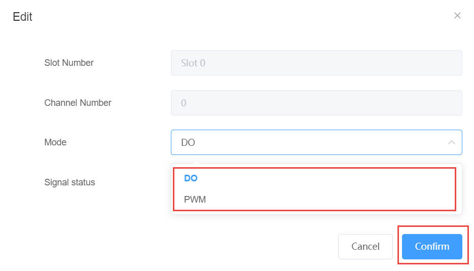
Mode: Normal (i.e. DO) or PWM.
-
Signal Status: DO port level value.
-
Value: When in Normal mode, the output DO value is displayed here; Counter mode, the count value is displayed here.
-
Low width: The low level pulse width of the output in PWM mode.
-
High width: The high-level pulse width of the output in PWM mode.
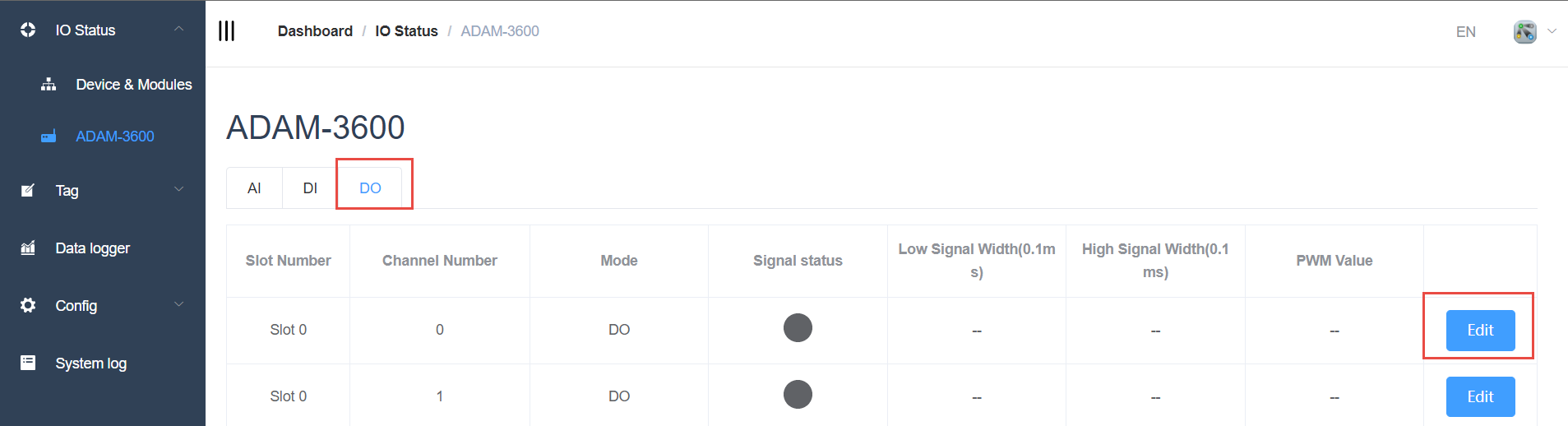
If you need to configure, click the Edit button to set the DO channel mode to DO or PWM
-
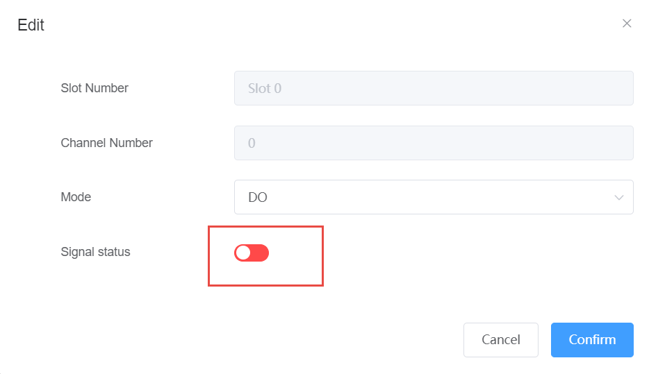
DO mode: Set the DO output by clicking the signal status, green is high, red is low.
-
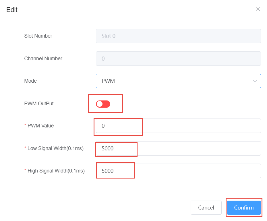
PWM mode:
-
PWM output: green is enabled, red is not enabled
-
PWM value: Set the number of output PWM waveforms, the default is 0, 0 means always output
-
Low signal width: The low level pulse width of the output PWM in 0.1ms, and the pulse width is (0.1* number) ms
-
High signal width: The high level pulse width of the output PWM is 0.1ms, and the pulse width is (0.1* number) ms